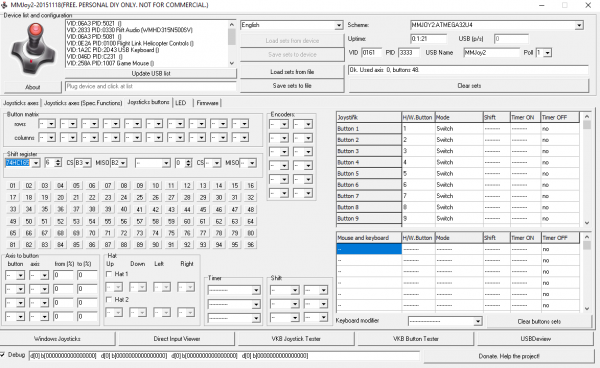
Shift Register
Many newcomers to building switch panels get caught up in trying to understand switch matrixes.....until they discover shift registers
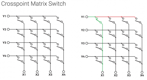
Switch Matrix
A shift matrix is basicaly a grid, 2x2, 3x3, 4x4....6x8, 5x7, 8 x 8  (They dont have to have the same number of rows and columns)
the benefit is you get the number of switches (a multiple of the two numbers, e.g. in the example above,   4 x 4= 16 buttons)
for a meagre use of pins (the sum of the the 2 numbers e.g: 4 + 4 = 8 pins)
The Good: this a significant reduction of pins required, in this case its half, but that factor is exponentially increase with larger arrays (8x8=64 switches / 8+8=16 pins)
The Bad: its a complicated wiring process, transferring the logical pinout on the schematic to a physical wiring mesh...
The Ugly: you need to include individual diodes after each switch to prevent such anomalies as ghosting and masking
For further information on understanding Switch Matrix and the issues associated with them read this excellent reference:
https://www.dribin.org/dave/keyboard/one_html/
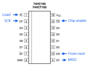
Shift Register
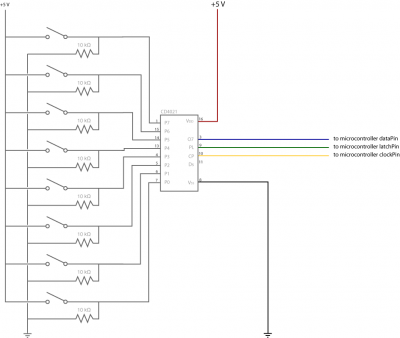
Where as a shift register will allow you to connect 8 switches per chip
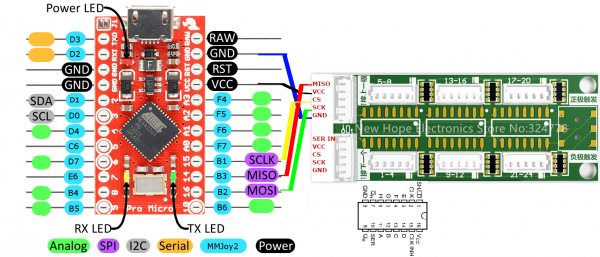
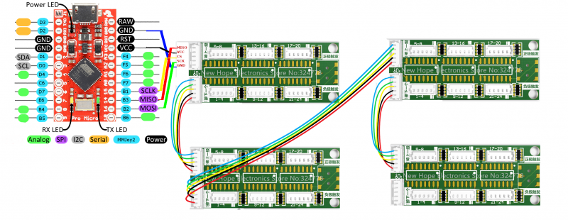
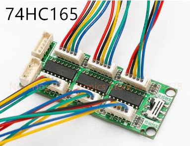
These boards have 3 chips so (3 x 8) 24 buttons per board..... and only requires 5 wires coming back to the controller card
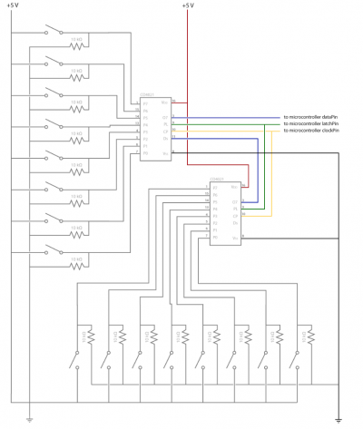
and thats not all, you can daisy chain these shift registers together, and have 2, 3 or 4 connected, (giving you 48, 72 or 96 switches) all running back to your USB controller only on 5 wires to 5 pins.
Note: a switch matrix would require 20 wires back to 20 pins to achieve the same result
Note: the pro micro controller card has a limit of 96 switches,
I tend to limit my panels and wiring to ~64 switches, which is usually ample with still some spare
So the obvious benefit; limited to just 5 wires;
- using a switch matrix, I'd be limited to a maximum of 6 switches (3x2 matrix)
- utilising a shift register, I'd have a minimum of 24 switches available (3x8 chips) on a single board, (multiplied by as many shift register boards as I had available)
Wiring
The other benefit with the shift registers is that there is no need for messy placement of diodes in line to prevent ghosting/masking of switch inputs.
Each chip is located on a board with a Resistor Network, this ensures there is no noise that could be interpreted as (false positive) button inputs
Shared Ground
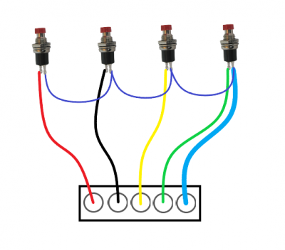
The trick with the shift registers is wiring the shared ground between each set of switches on a particular chip
there are 8 inputs on each chip on the shift register board (in the example above D0 - D7) but there is only one Ground
therefore you must daisy chain all the ground pins on the 8 switches connected to this chip together and then connect them to the Ground pin (on a single bus)
e.g. in the example board above, simple wire each of the wires to a switch, then wire all the grounds from each switch together
now connect the ground (blue wire pictured in this instance) to one of those joined ground switches ....jobs done
Each of the 3 chips on the shift register board are the same, 8 switches, single ground, wire ground pins on all 8 switches together, then back to single ground on the chip.
Shift Registers are by far the simplest method of connecting multiple switches on DIY panels for less than US$10, accompanied with MMJoy2 on a ATMega32U4 chip controller card, like the generic Pro Micro (less than US$5), it is by far the most cost effective.
Flash the Pro Micro to run BIOS for use with the MMJoy software, will make configuration and usage MUCH simpler for newbies.
Remember: "when soldering - don't be on fire"
